KG7CR "NWQRP Special"
30mtr 5w CW TX
This 1993 Northwest QRP Club Project enabled many to check into the Club net on 10.123 mhz. It was easy to build, and had simple instructions including a helpful torroid winding diagram. Mine worked first time and is still working today! The kit is nolonger availiable and the Club nolonger exists.
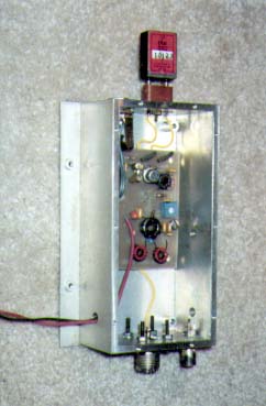
The transmitter is shown in an aluminum box with an FT-243 crystal socket and key jack on the front. There are 2 RF jacks on the back, an SO-239 type for the antenna, and a BNC for the antenna output to the RX via a PIN diode switch circuit that is not shown.
The circuit uses an NPN transistor oscillator, 2N3866, 2N5103 or 2N2219 transformer coupled to an IRF510 Pwr FET as the RF amplifier. A two section output filter is used. The PCB supplied by NWQRP Club was thoughtful in it's design and lent itself easily to future modifications. Common modifications were sidetone, TR switch, and keying characteristics modifications.
At WB6FZH a second transmitter was built with switch to change the output filter for other bands (80/40). The broadband design lent itself easily to other frequencies. At 12 volts the output is a solid 5w. Bruce Franklin, the designer, NWQRP Technical Editor & Father of the QRP+, said that if you increase the IRF510's supply voltage to 18 volts, that almost 18 watts is availiable to a properly heatsinked output stage.
SCHEMATIC will be added to this article in 2009.
10/15/94
Last Updated:- January 20, 2009
VISIT THE WB6FZH WEBSITE- Eventually this and other articles will be consolidated there with new content.